Burning a bootloader onto an ATmega328P-AU (SMD version) involves programming the chip using an In-System Programming (ISP) interface. Below is a detailed guide:
Tools and Components Needed:
- ATmega328P-AU (SMD chip) mounted on a breakout board or custom PCB.
- ISP Programmer (e.g., USBasp, Arduino as ISP, or other AVR-compatible programmers).
- 6-pin ISP header on your PCB (connected to the ATmega328P-AU).
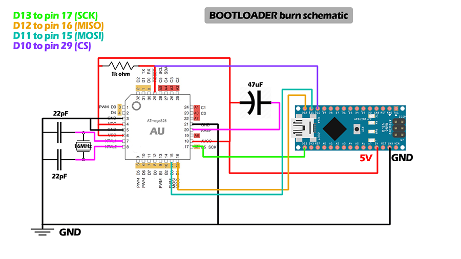
- External 16 MHz Crystal (if you're using the ATmega328P with the Arduino bootloader and need an external clock).
- Capacitors:
- Two 22 pF capacitors (for the crystal).
- A 0.1 µF decoupling capacitor near the VCC and GND pins.
- Pull-up Resistor:
- A 10 kΩ pull-up resistor on the RESET pin.
- Software:
- Arduino IDE or AVRDUDE (for advanced users).
- Bootloader files (e.g., Arduino bootloader for ATmega328P).
Steps to Burn the Bootloader:
Step 1: Hardware Connections
Connect your ISP programmer to the ATmega328P-AU using the following pin mapping:
| ISP Pin |
ATmega328P Pin |
Description |
| MISO |
Pin 18 (PB4) |
Master In Slave Out |
| MOSI |
Pin 17 (PB3) |
Master Out Slave In |
| SCK |
Pin 19 (PB5) |
Serial Clock |
| RESET |
Pin 1 |
Reset |
| VCC |
Pin 7 (AVCC) and Pin 20 |
Supply Voltage (5V or 3.3V) |
| GND |
Pin 8 (GND) and Pin 22 |
Ground |
- Connect an external 16 MHz crystal between pins 9 (XTAL1) and 10 (XTAL2) with 22 pF capacitors connected to ground.
- Add a 10 kΩ pull-up resistor between the RESET pin and VCC.
Step 2: Configure the Software
-
Using Arduino IDE:
- Connect your programmer to the computer via USB.
- Open the Arduino IDE and go to Tools > Board. Select "Arduino Uno" (if you're using an Arduino-compatible bootloader).
- Select your Programmer from Tools > Programmer (e.g., "USBasp" or "Arduino as ISP").
- Go to Tools > Burn Bootloader. This will configure the fuses and upload the bootloader.
-
Using AVRDUDE (Command-line option):
- Install AVRDUDE.
- Use the following command to burn the bootloader:
- Replace
<programmer> with your programmer type (e.g., usbasp).
- Replace
<bootloader.hex> with the path to your bootloader file.
- Configure fuse values:
- For 16 MHz external crystal:
- Low Fuse:
0xFF
- High Fuse:
0xDE
- Extended Fuse:
0xFD
Step 3: Verify Bootloader
- After burning the bootloader, you can verify it by uploading a simple sketch (like Blink) using the serial interface. If the upload works, the bootloader was successfully burned.
Tips and Troubleshooting:
- Power Supply:
- Ensure the chip is properly powered (3.3V or 5V, depending on your configuration).
- Check Connections:
- Verify all connections are secure, especially the ISP pins.
- Fuse Settings:
- Make sure the fuses are set correctly for your clock source (internal RC oscillator or external crystal).
- Crystal Oscillator:
- If you're using an external crystal, double-check its placement and the associated capacitors.
By following these steps, you can successfully burn a bootloader onto an ATmega328P-AU (SMD version) and prepare it for use in your project.