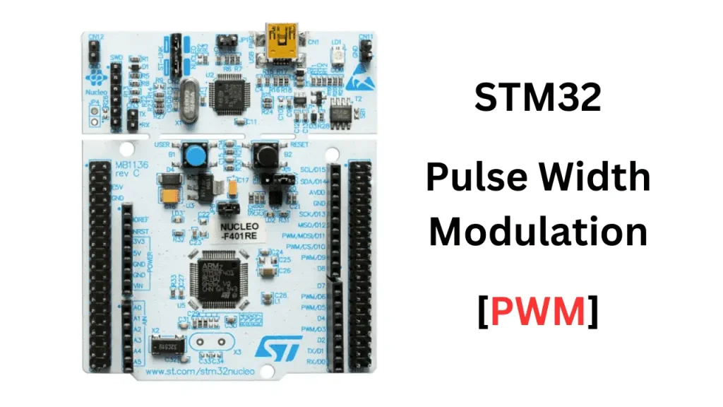
STM32 PWM Principle and Application
Global electronic component supplier AMPHEO PTY LTD: Rich inventory for one-stop shopping. Inquire easily, and receive fast, customized solutions and quotes.
PWM (Pulse Width Modulation) is a fundamental technique used in STM32 and other microcontrollers for controlling analog-like behavior using digital signals. It is widely used in applications such as motor control, LED brightness, audio signal generation, and more.

🔧 STM32 PWM Principle
✅ What is PWM?
PWM is a digital signal with a fixed frequency but variable duty cycle.
-
Frequency: How often the signal repeats (e.g. 1 kHz = 1000 times per second)
-
Duty Cycle: The percentage of time the signal is HIGH in one period.
Example:
-
0% Duty Cycle → Always LOW
-
50% Duty Cycle → Half HIGH, half LOW
-
100% Duty Cycle → Always HIGH
✅ How STM32 Generates PWM
STM32 uses Timers in PWM mode to generate signals:
-
Timer counts up to a value (ARR - Auto Reload Register).
-
When counter reaches a compare value (CCR - Capture Compare Register), the output pin toggles.
-
The compare value defines the duty cycle.
📐 PWM Formula
For a timer in up-counting mode:
-
PWM Frequency =
Timer Clock / ((PSC + 1) * (ARR + 1)) -
Duty Cycle (%) =
(CCR / ARR) * 100
Where:
-
PSC= Prescaler -
ARR= Auto Reload Register -
CCR= Capture Compare Register
🛠️ Application Example: LED Brightness Control
🧱 Hardware
-
STM32F4 board
-
LED connected to a PWM-capable pin (e.g., TIM3_CH1)
⚙️ Setup in STM32CubeMX
-
Select Timer (e.g., TIM3)
-
Enable a PWM Channel (e.g., CH1) on a pin (e.g., PB4)
-
Set the timer prescaler and period (ARR) to define frequency.
-
Enable GPIO as alternate function.
-
In the generated code, use
__HAL_TIM_SET_COMPARE()to control duty cycle.
📄 Example Code
🎯 Common Applications
| Application | Description |
|---|---|
| LED Dimming | Change brightness by varying duty cycle |
| Motor Control | Control speed or direction (via H-bridge) |
| Servo Control | Generate 1–2 ms pulse at 50 Hz for position |
| Audio | Generate tones by varying frequency |
| Power Supplies | Use PWM in SMPS for voltage regulation |
📚 Conclusion
PWM in STM32 is implemented using timers, offering high precision and flexibility. It's simple to configure with CubeMX and powerful enough for real-time control tasks like dimming, speed regulation, and signal generation.
Related Articles
- ·What are the differences between popular MCU families (e.g., ARM Cortex-M, AVR, PIC, ESP32)?
- ·STM32 four precision control methods for stepper motors
- ·What is the lowest power STM32 MCU? how to choose?
- ·Blue Pill vs Black Pill: What’s the Difference and How to Choose?
- ·Why can STM32 stand out from many 32-bit microcontrollers?
- ·How to distinguish fake chips?
- ·How do I secure an MCU from hacking or tampering?
- ·What are the advantages and disadvantages of using SoCs in embedded systems?
- ·How to implement a multi class neural network with STM32F103?
- ·Comparison of ARM vs. RISC-V MCUs
