


How to determine the performance limit of a microcontroller?

Global electronic component supplier AMPHEO PTY LTD: Rich inventory for one-stop shopping. Inquire easily, and receive fast, customized solutions and quotes.
Determining the performance limit of a microcontroller (MCU) is crucial for ensuring it meets the requirements of a robot motion control system. Here are the key factors and methods to evaluate an MCU's performance limits:
1. Key Performance Metrics
1.1 Clock Speed (MHz/GHz)
-
Definition: The number of cycles the MCU can execute per second.
-
Impact: Higher clock speeds generally mean faster execution but also higher power consumption.
-
Limitation: Not all instructions take 1 cycle; check the CPI (Clocks Per Instruction).
1.2 MIPS (Million Instructions Per Second)
-
Formula:
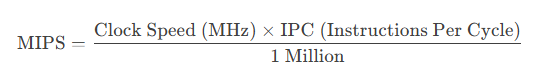
- Example:
-
ARM Cortex-M4 @ 100 MHz ≈ 125 MIPS (1.25 DMIPS/MHz × 100 MHz)
-
Cortex-M7 @ 216 MHz ≈ 462 MIPS (2.14 DMIPS/MHz × 216 MHz)
-
1.3 DMIPS (Dhrystone MIPS)
-
A standardized benchmark for comparing CPU performance.
-
Reference:
-
Cortex-M0: 0.9 DMIPS/MHz
-
Cortex-M4: 1.25 DMIPS/MHz
-
Cortex-M7: 2.14 DMIPS/MHz
-
1.4 FLOPS (Floating-Point Operations Per Second)
-
Critical for control algorithms (PID, kinematics, filtering).
-
Example:
-
Cortex-M4 (with FPU) ≈ 1.5 MFLOPS @ 100 MHz
-
Cortex-M7 (with FPU) ≈ 5+ MFLOPS @ 216 MHz
-
1.5 Memory Constraints
-
Flash/ROM: Code size limits (e.g., 512 KB vs. 2 MB).
-
RAM: Real-time data processing (e.g., 128 KB vs. 1 MB).
-
Cache: Cortex-M7 has instruction/data cache (faster execution).
1.6 Peripheral Throughput
-
PWM Resolution: 16-bit vs. 8-bit (affects motor control precision).
-
ADC Speed: 1 MSPS vs. 5 MSPS (for fast sensor feedback).
-
Communication Speed:
-
SPI (50 MHz vs. 100 MHz)
-
CAN FD (5 Mbps vs. classic 1 Mbps)
-
2. Methods to Determine Performance Limits
2.1 Benchmarking
-
Dhrystone: Measures integer performance (DMIPS).
-
CoreMark: More modern than Dhrystone, better for embedded systems.
-
Whetstone: Measures floating-point performance (FLOPS).
2.2 Real-World Testing
-
Control Loop Timing:
-
Measure the time to execute a PID loop (e.g., 10 µs @ 100 MHz).
-
Use an oscilloscope to check interrupt latency.
-
-
DMA vs. CPU Transfer:
-
Compare sensor data reading via polling vs. DMA.
-
2.3 Worst-Case Execution Time (WCET) Analysis
-
Static Analysis:
-
Disassemble code and count cycles for critical functions.
-
-
Dynamic Analysis:
-
Use a logic analyzer to measure execution time under stress.
-
2.4 Power vs. Performance Tradeoff
-
Dynamic Voltage & Frequency Scaling (DVFS):
-
Lower clock speed saves power but reduces MIPS.
-
-
Sleep Modes:
-
If the MCU sleeps between control cycles, check wake-up latency.
-
3. Performance Bottlenecks in Robotics
3.1 Motor Control Loop Frequency
-
Requirement:
-
Current Loop: 10–20 kHz (50–100 µs per cycle).
-
Position Loop: 100–500 Hz (2–10 ms per cycle).
-
-
MCU Limitation:
-
If an M4 @ 100 MHz takes 80 µs for PID, it can’t run at 20 kHz.
-
3.2 Sensor Fusion (IMU + Encoders)
-
Kalman Filter Computation:
-
A 6-state Kalman filter may take 200 µs on M4 but 50 µs on M7.
-
3.3 Communication Overhead
-
CAN Bus: 1 Mbps may limit real-time control in multi-axis robots.
-
SPI for Encoders: 10 MHz vs. 50 MHz affects response time.
4. Example: Cortex-M4 vs. M7 for Robotics
| Metric | Cortex-M4 (100 MHz) | Cortex-M7 (216 MHz) |
|---|---|---|
| DMIPS | 125 | 462 |
| FPU Speed | ~1.5 MFLOPS | ~5 MFLOPS |
| PID Loop Time | 80 µs | 20 µs |
| Max PWM Freq | 50 kHz (16-bit) | 100 kHz (16-bit) |
| Power (mA) | 30 mA (active) | 80 mA (active) |
Conclusion:
-
M4 is sufficient for simple robots (e.g., 2-DOF arms).
-
M7 is needed for high-speed control (e.g., drones, humanoids).
5. Tools for Performance Analysis
-
Keil MDK / IAR: Profiling tools to measure CPU load.
-
FreeRTOS Tracealyzer: Visualizes task execution timing.
-
Logic Analyzer (Saleae): Measures interrupt latency.
-
STM32CubeMonitor: Real-time power & performance tracking.
Final Recommendation
To determine if an MCU meets your robot’s needs:
-
Benchmark (CoreMark, Dhrystone).
-
Measure real-time control loop speed.
-
Check memory & peripheral bottlenecks.
-
Validate worst-case latency.
If the MCU can’t meet timing requirements, consider:
✔ Upgrading to a faster core (M7, dual-core)
✔ Offloading tasks to FPGA/CPLD
✔ Using DMA to reduce CPU load
Related Articles
- ·How do I secure an MCU from hacking or tampering?
- ·The best MCUs/MPUs for industrial humanoid robots
- ·Comparison of ARM vs. RISC-V MCUs
- ·ESP32 vs Arduino, Compare their differences and use cases
- ·The Application of Embedded Electronics in the Field of Consumer Electronics
- ·The application of embedded systems in the field of automotive electronics
- ·Make an MP3 player based on AVR microcontroller
- ·How many programming methods are there for the STM32G431RBT6 microcontroller?
- ·Design of solar automatic light tracking system