


How to use STM32 as a logic analyzer?

Global electronic component supplier AMPHEO PTY LTD: Rich inventory for one-stop shopping. Inquire easily, and receive fast, customized solutions and quotes.
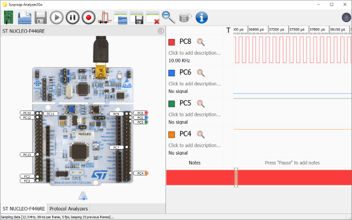
You can turn an STM32 microcontroller into a basic logic analyzer to capture and analyze digital signals. Here's how to implement this:
Hardware Requirements
-
STM32 board (F3/F4/H7 series recommended for better performance)
-
Input protection circuitry (optional but recommended - diodes, resistors)
-
Host computer for data analysis
Software Approaches
1. Using Serial Communication (Basic)
Method:
-
Configure GPIO pins in input mode
-
Sample inputs at fixed intervals
-
Send data via UART/USB to PC
Example Code:
#define SAMPLE_PIN PA0
#define SAMPLE_RATE 100000 // 100 kHz

void setup() {
  pinMode(SAMPLE_PIN, INPUT);
  Serial.begin(115200);
}

void loop() {
  static uint32_t lastTime = 0;
  if (micros() - lastTime >= (1000000/SAMPLE_RATE)) {
    lastTime = micros();
    Serial.println(digitalRead(SAMPLE_PIN));
  }
}
2. Using Timer Interrupts (Better Performance)
volatile uint8_t samples[1000];
volatile uint16_t sampleIndex = 0;

void setup() {
  pinMode(PA0, INPUT);
  TIM_TypeDef *Instance = TIM2;
  HardwareTimer *MyTim = new HardwareTimer(Instance);
  MyTim->setOverflow(100000, HERTZ_FORMAT); // 100 kHz sampling
  MyTim->attachInterrupt(sampleISR);
  MyTim->resume();
}

void sampleISR() {
  if(sampleIndex < 1000) {
    samples[sampleIndex++] = digitalRead(PA0);
  }
}

void loop() {
  if(sampleIndex >= 1000) {
    for(int i=0; i<1000; i++) {
      Serial.println(samples[i]);
    }
    sampleIndex = 0;
  }
}
3. Using DMA (Highest Performance)
For STM32H7/F7/F4 with DMA:
-
Configure timer to trigger DMA transfers
-
DMA writes directly to memory buffer
-
Can achieve 10-50 MHz sampling on multiple channels
PC-Side Visualization Options
-
Sigrok/PulseView:
-
Use the "serial" or "UART" input option
-
Configure baud rate and data format
-
-
Custom Python Script:
import serial
import matplotlib.pyplot as plt

ser = serial.Serial('COM3', 115200)
data = []
for _ in range(1000):
    data.append(int(ser.readline().decode().strip()))

plt.plot(data)
plt.show()
-
Arduino Serial Plotter:
-
Simple but limited to slower sample rates
Advanced Techniques
-
Multiple Channels:
-
Use GPIO port input register to read up to 16 pins simultaneously
-
Example:
uint16_t port_data = GPIOA->IDR;
-
-
Trigger Conditions:
-
Implement hardware/comparator based triggers
-
Capture pre-trigger and post-trigger data
-
-
Timing Accuracy:
-
Use hardware timers for precise sampling intervals
-
STM32's timer peripherals can trigger DMA transfers
-
Limitations
Related Articles
- ·What are the differences between popular MCU families (e.g., ARM Cortex-M, AVR, PIC, ESP32)?
- ·STM32 four precision control methods for stepper motors
- ·What is the lowest power STM32 MCU? how to choose?
- ·Blue Pill vs Black Pill: What’s the Difference and How to Choose?
- ·Why can STM32 stand out from many 32-bit microcontrollers?
- ·How to distinguish fake chips?
- ·How do I secure an MCU from hacking or tampering?
- ·The best MCUs/MPUs for industrial humanoid robots
- ·What are the advantages and disadvantages of using SoCs in embedded systems?
- ·How to implement a multi class neural network with STM32F103?