


DS18B20 Temperature Sensor Detailed Explanation and Use Cases

Global electronic component supplier AMPHEO PTY LTD: Rich inventory for one-stop shopping. Inquire easily, and receive fast, customized solutions and quotes.
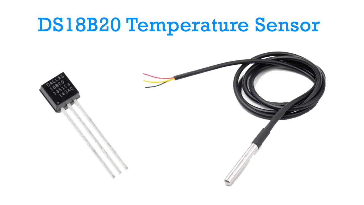
DS18B20 Temperature Sensor Overview
The DS18B20 is a digital temperature sensor from Maxim Integrated that provides high accuracy, a simple interface, and unique device identification, making it a top choice in embedded and IoT applications.
Key Features
| Feature | Details |
|---|---|
| Temperature Range | -55°C to +125°C |
| Accuracy | ±0.5°C (from -10°C to +85°C) |
| Resolution | Programmable: 9 to 12 bits |
| Interface | 1-Wire Digital Communication |
| Supply Voltage | 3.0V to 5.5V |
| Power Modes | Normal (VDD) and Parasitic Power |
| Unique ID | 64-bit serial number for each device |
| Package Options | TO-92, waterproof sealed, SMD |
1-Wire Communication Protocol
The DS18B20 uses 1-Wire protocol, which allows data transmission and even power over a single wire, plus ground.
Basic Operation Flow
-
Reset pulse by the master.
-
Presence pulse from the DS18B20.
-
Master sends a ROM command (e.g.,
Match ROM,Skip ROM). -
Master sends a function command (e.g.,
Convert T,Read Scratchpad). -
Sensor responds with temperature or status data.
ROM Commands
-
Read ROM: Read device's unique 64-bit ID. -
Match ROM: Select a specific sensor on the bus. -
Skip ROM: Broadcast to all sensors. -
Search ROM: Identify all sensors on the bus.
Internal Memory (Scratchpad)
The DS18B20 has a 9-byte scratchpad memory, structured as:
| Byte | Content |
|---|---|
| 0 | Temperature LSB |
| 1 | Temperature MSB |
| 2 | TH (Alarm High) |
| 3 | TL (Alarm Low) |
| 4 | Configuration Register |
| 5–7 | Reserved |
| 8 | CRC |
The configuration register allows you to set the resolution:
| Resolution | Temp Step | Conversion Time (typical) |
|---|---|---|
| 9-bit | 0.5°C | 93.75 ms |
| 10-bit | 0.25°C | 187.5 ms |
| 11-bit | 0.125°C | 375 ms |
| 12-bit | 0.0625°C | 750 ms |
Temperature Reading Formula
After reading the temperature bytes:
Powering Modes
1. Normal Mode
-
VDD connected to 3.0–5.5V.
-
DQ (data) connected with a 4.7kΩ pull-up resistor.
2. Parasitic Mode
-
Only DQ and GND are used.
-
Sensor steals power during the high state of the data line.
-
Requires careful timing during conversions.
Typical Circuit
Advantages
-
Minimal wiring (1-Wire).
-
Easily network multiple sensors on one bus.
-
Accurate and stable digital output.
-
Waterproof versions for harsh environments.
-
Programmable resolution and alarms.
Common Use Cases
Scientific and Industrial
-
Lab temperature monitoring
-
Industrial machinery thermal monitoring
-
Process control systems
Home Automation
-
Smart thermostats
-
Room-based climate control
-
Floor heating systems
Agriculture and Environment
-
Greenhouse temperature control
-
Soil temperature monitoring
-
Weather stations
Liquid Immersion and Waterproof Applications
-
Aquarium temperature sensing
-
Water tank monitoring
-
Food storage and cold chain logistics
Data Logging
-
Long-term temperature data collection
-
Solar panel performance tracking
-
Refrigeration monitoring systems
Development Platforms
Supported on most microcontroller platforms:
-
Arduino: Uses libraries like
OneWireandDallasTemperature. -
STM32: Uses custom 1-Wire or HAL/GPIO-based implementations.
-
Raspberry Pi: Accessible via GPIO with Python (e.g., using
w1thermsensor). -
ESP32: Great for IoT applications; supports DS18B20 over Wi-Fi.
Related Articles
- ·What are the differences between popular MCU families (e.g., ARM Cortex-M, AVR, PIC, ESP32)?
- ·How do you choose the right sensor for a project?
- ·What are some common Arduino projects for beginners?
- ·How do you set up a Raspberry Pi as a VPN server?
- ·STM32 four precision control methods for stepper motors
- ·What is the lowest power STM32 MCU? how to choose?
- ·Blue Pill vs Black Pill: What’s the Difference and How to Choose?
- ·Why can STM32 stand out from many 32-bit microcontrollers?
- ·Why can Arm chips change today's world?
- ·How to distinguish fake chips?