


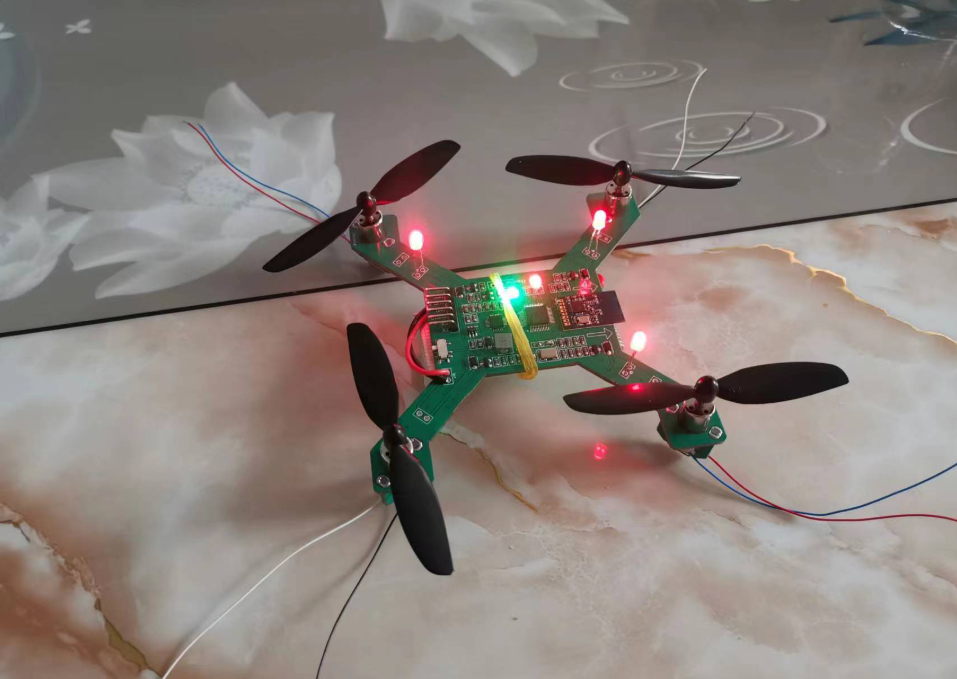
Using STM32 to produce multi-rotor UAV (Unmanned Aerial Vehicle)

Global electronic component supplier AMPHEO PTY LTD: Rich inventory for one-stop shopping. Inquire easily, and receive fast, customized solutions and quotes.
Using STM32 microcontrollers to develop a multi-rotor UAV (Unmanned Aerial Vehicle) is a popular choice due to their real-time processing capabilities, peripheral support, and robustness. Below is a structured guide on how to approach this project:
1. Hardware Selection
A. STM32 MCU Options
-
STM32F4/F7/H7 Series (High Performance, Floating-Point Support)
-
STM32G4 Series (Balanced Performance & Power Efficiency)
-
STM32F1/F0 Series (Basic Quadcopters, Less Complex Control)
B. Essential Components
-
Flight Controller Board (Custom PCB or Development Board like Nucleo-STM32H743)
-
IMU (Inertial Measurement Unit) – MPU6050 (Accel + Gyro), BMI270, ICM-42605, or BNO055 (9-DOF)
-
Barometer (MS5611, BMP280) – For altitude hold
-
Magnetometer (HMC5883L, QMC5883) – For heading
-
ESC (Electronic Speed Controller) – BLHeli_S / BLHeli_32 (for Brushless Motors)
-
Motors & Propellers – KV rating depends on UAV size (e.g., 1000KV for 5" drones)
-
Battery – LiPo (3S-6S, depending on motor requirements)
-
Radio Receiver (PPM/SBUS/CRSF – e.g., FrSky X4R, ELRS)
-
Telemetry (Optional) – ESP8266/NRF24L01 for wireless data
2. Software Development
A. Firmware Development
-
RTOS (Real-Time OS) – Use FreeRTOS or ChibiOS for task scheduling.
-
Sensor Fusion – Implement Madgwick/Mahony AHRS or Kalman Filter for attitude estimation.
-
PID Control – For motor stabilization (Roll, Pitch, Yaw).
-
PWM Output – Use STM32 TIMER + DMA for ESC control (OneShot125, DShot protocol).
-
Communication Protocols:
-
I2C/SPI (IMU, Barometer)
-
UART (GPS, Telemetry, Receiver)
-
CAN Bus (Advanced ESCs)
-
B. Development Tools
-
IDE: STM32CubeIDE (Free, HAL/LL Support)
-
Libraries:
-
STM32 HAL/LL (Hardware Abstraction Layer)
-
Betaflight/INAV (Open-Source Reference) (Study their STM32 implementations)
-
-
Debugging: ST-Link, Logic Analyzer, UART Printf
3. Flight Control Algorithm
A. Basic Control Loop
-
Read Sensors (IMU, Barometer, Magnetometer)
-
Sensor Fusion (Compute Roll, Pitch, Yaw)
-
PID Controller (Adjust motor speeds based on error)
-
ESC Signal Generation (PWM/DShot)
B. Advanced Features (Optional)
-
GPS Navigation (Waypoint Following, Return-to-Home)
-
Obstacle Avoidance (Ultrasonic/LiDAR)
-
Computer Vision (OpenMV, ESP32-CAM)
-
Wireless Telemetry (MAVLink Protocol)
4. Example Code Snippet (STM32 + MPU6050 + PID)
// STM32 HAL-based PID Motor Control (Simplified)
#include "stm32f4xx_hal.h"
#include "mpu6050.h"  // MPU6050 Driver

// PID Gains
float Kp = 1.2, Ki = 0.5, Kd = 0.1;
float roll_error, pitch_error, yaw_error;

void IMU_Update() {
  MPU6050_Read_Data(&accel, &gyro);  // Read IMU
  MadgwickAHRSupdate(gyro.x, gyro.y, gyro.z, accel.x, accel.y, accel.z); // Sensor Fusion
}

void PID_Control() {
  roll_error = target_roll - current_roll;
  pitch_error = target_pitch - current_pitch;
  yaw_error = target_yaw - current_yaw;

  // Compute PID Output
  float roll_output = Kp * roll_error + Ki * roll_integral + Kd * (roll_error - prev_roll_error);
  float pitch_output = Kp * pitch_error + Ki * pitch_integral + Kd * (pitch_error - prev_pitch_error);

  // Adjust Motor Speeds (4 Motors)
  motor1 = throttle + roll_output + pitch_output;
  motor2 = throttle - roll_output + pitch_output;
  motor3 = throttle - roll_output - pitch_output;
  motor4 = throttle + roll_output - pitch_output;

  // Apply PWM to ESCs
  __HAL_TIM_SET_COMPARE(&htim3, TIM_CHANNEL_1, motor1);
  __HAL_TIM_SET_COMPARE(&htim3, TIM_CHANNEL_2, motor2);
  // ... (Other Motors)
}

int main(void) {
  HAL_Init();
  MPU6050_Init();
  while (1) {
    IMU_Update();
    PID_Control();
    HAL_Delay(2);  // ~500Hz Loop
  }
}
5. Testing & Calibration
-
Motor Testing – Ensure correct spin direction.
-
PID Tuning – Start with small gains, increase gradually.
-
IMU Calibration – Eliminate bias in gyro/accel.
-
Radio Calibration – Verify stick inputs (1000-2000µs PWM range).
6. Safety Considerations
-
Fail-Safes (Signal Loss → Hover/Land)
-
Battery Monitoring (Voltage Check)
-
Propeller Guards (For Indoor Testing)
Conclusion
Building a multi-rotor UAV with STM32 involves:
✅ Selecting the right STM32 MCU (F4/F7/H7 recommended)
✅ Integrating IMU, ESCs, and Radio Receiver
✅ Writing firmware with Sensor Fusion + PID Control
✅ Testing and tuning for stable flight
For faster development, consider studying open-source flight controllers like Betaflight, iNav, or ArduPilot (many use STM32).
Related Articles
- ·What are the advantages and disadvantages of using SoCs in embedded systems?
- ·How to implement a multi class neural network with STM32F103?
- ·Comparison of ARM vs. RISC-V MCUs
- ·How to achieve serial communication between STM32 and ESP8266?
- ·SoC vs SoM: What's the Difference?
- ·DS18B20 Temperature Sensor Detailed Explanation and Use Cases
- ·How to deploy artificial intelligence algorithms on STM32?
- ·The Difference Between 8-bit, 16-bit, 32-bit, And 64-bit Microcontrollers
- ·STM32 PWM Principle and Application
- ·How to use STM32 as a logic analyzer?