


What is Verilog?: Module, Multiplexer, and Verilog vs. Vhdl
August 02 2023 
Inquiry
Global electronic component supplier AMPHEO PTY LTD: Rich inventory for one-stop shopping. Inquire easily, and receive fast, customized solutions and quotes.
QUICK RFQ
ADD TO RFQ LIST
This article is going to make detailed introduction about Verilog including Verilog Module, Decoder, Multiplexer, Verilog vs. Vhdl, and so on.
What is Verilog?
A hardware description language is Verilog. (HDL). This language, along with its rival VHDL, is the most used one for programming FPGAs. Why would you want to learn a difficult programming language when you can program an FPGA using a schematic that you are likely already familiar with and understand? The truth is that, as designs get more complex, it's actually simpler to represent them in a programming language than it is to draw them. Verilog has features that are similar to those found in programming languages, such as "if" statements, code blocks, and the ability to add and subtract numbers.Verilog Tutorial
Verilog Module
Software developers will notice that a Verilog module resembles an object-oriented programming class. It defines a set of logic that may be instantiated several times in your design and has both public and private characteristics. If you prefer electronics, consider a module as a subassembly of the design with well-defined connections that allow it to be connected to other modules or, if you prefer, an IC. When things get a little more complicated, a simple design might be contained entirely within a single module instead of becoming a collection of interconnected modules. You will be able to use other people's modules in your designs if you do it this way.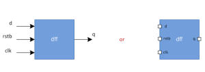
A Seven-Segment Decoder
A type of electronic display device for showing decimal numbers is a seven-segment display (SSD). They can be used in place of intricate displays like dot matrices. An SSD contains 7 segments, thus we could theoretically use it to show 27 = 128 character combinations. However, the majority of these combinations are confusing to human sight. On a 7-segment panel, decimal numerals can be represented appropriately as demonstrated below: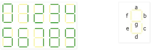
Button Debouncing
You might have observed some switch bounce while experimenting with the counter project, which led the counter to skip over some numbers. By developing a debouncing module that can be applied to any project involving a switch, we can take action to address this issue. There are actually three issues that need to be resolved when it comes to pushing switches. The first issue is that a button press will never be synchronized with the clock by design. The second issue is how to genuinely eliminate any unwanted transitions brought on by the switch's mechanical contacts bouncing.Verilog Multiplexer
The three major methods for building a multiplexer are as follows. Logic gates make up digital multiplexers, transistors go into analog multiplexers, and spinning shafts go into mechanical or rotary switches. The MUX itself functions as a digitally controlled multi-position switch where the data input is controlled by the binary code applied to the selected inputs and switched to the output. For instance, based on the select signal, it sends data from one of the N inputs to the output. Each of the N 4-bit inputs of a 4-bit multiplexer can be sent to the output by means of a select signal. Sel can have four different values and is a 2-bit input. Each value on the select line will allow one of the inputs to be sent to the output.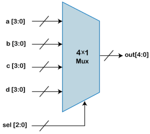
Verilog Wires, Registers, and Buses
In Verilog, what are called wires (which link things together) or registers (which hold state and are more akin to variables in programming languages) are what would be variables in a traditional programming language. A single binary digit is referred to as a wire and a register. A vector is a collection of bits that can be used to perform operations on the vector as a whole when working on several bits at once. This is comparable to utilizing arbitrary-length words in a traditional programming language. The upper and lower bits are supplied when such vectors are defined. The example that follows illustrates an 8-bit counter: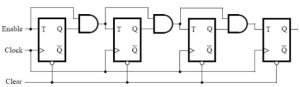
Verilog integer constants
When working with a vector in Verilog, which you will do frequently, it is convenient to assign values using numbers of any bit size and radix. (number base). In order to do this, Verilog employs a unique number syntax. Unused bits are set to 0 and the number is assumed to be decimal if neither the number of bits nor the radix are specified. The number format is composed of the number of bits, an apostrophe, a radix indicator (b = binary, h = hex, and d = decimal), the number constant, and finally the number.Parallel Execution
Many times, controlling specific functional threads in parallel is necessary for design verification projects. These threads can be used to monitor activity on some parallel-running interfaces, control simultaneous stimuli, gather data for intricate coverage blocks, etc. In order to accomplish the ultimate verification objective using the verification features, a user must devise a fine and reliable control approach for all of these concurrent functional threads.Verilog Synchronous Logic
The counter-example that came before it shows how simple it is to define some hardware in Verilog. However, it lacks a crucial component that is included in practically every Verilog example you want to look at. In other words, it is not time-synchronized. Because it is so easy, the sample only works in this case. The issue arises as soon as projects get even a little bit more complicated than this because signals move through logic gates at varying speeds, which means that an output that depends on inputs from numerous other system components and possibly even the output itself will take some time to reach its final value. It may have glitchy pulses that should be ignored by other parts of the system. Such outputs are described as metastable. Due to the fact that we are using the clock input to the counter as a general input connected to a switch rather than as a synchronizing clock input, you may have noticed some warning warnings when you constructed the project.Verilog Timing Control
In order to advance time in simulation, timing control statements are necessary. Timing controls are used to specify when procedural statements will be executed. The timing controls in Verilog listed below include Named events, Edge sensitive event control, Delay control, and Level sensitive event control. By using the delay control, you can delay the execution of the statement from the time the simulator meets it until after it executes. The @ character in Verilog designates an edge-sensitive event control that blocks until one of the event's identifiers experiences a change in value (an edge). Instead of a guard blocking while waiting for an edge event to occur, the edge events are queued and then handled by @(...) guards. A procedural statement's execution can be delayed until a condition becomes true and accomplished with the wait keyword. And it is a level-sensitive control.A Counter in Verilog
The counter is a digital sequential circuit that can count from 0 to 15 and vice versa depending on the direction of counting (up/down). In this case, the counter is a 4-bit counter. Every positive (rising) edge of the clock cycle will result in an evaluation of the counter ("count") value. When the "reset" input is set to logic high, the Counter will be reset to 0. When the "load" signal is logically high, the counter will be loaded with "data" input. If not, it will count upward or downward. If the "up_down" signal is logic high, the counter will count up; otherwise, it will count down.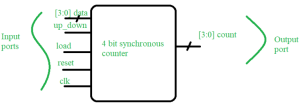
Verilog vs. SystemVerilog
Verilog is a Hardware Description Language (HDL), whereas System Verilog combines Hardware Verification Language (HVL) and Hardware Description Language (HDL). While SystemVerilog is used for planning, simulating, testing, and implementing electrical systems, the Verilog language is used to structure and model electronic systems. While the Verilog testbench is focused on module-level testing, SystemVerilog is based on the Class level testbench. Verilog needs the use of C and Fortran, but SystemVerilog is a programming language that combines Verilog, VHDL, and C++. Verilog only provides the datatypes Wire and Reg, in contrast to SystemVerilog, which also includes enum, union, struct, string, and class data types.Verilog vs. VHDL
| Verilog | VHDL |
| Strong typing is used in VHDL. This makes it more difficult for beginners to make mistakes because the compiler will prevent you from writing invalid code. | Verilog has weak typing, which enables you to create incorrect but shorter code. |
| Verilog resembles a programming language more closely than C. This makes reading and comprehending Verilog's operations simpler for someone proficient in C. | Although VHDL is more verbose and occupies more space, it tends to flow better and is simpler to understand as you read it. |
| Verilog is non-deterministic under certain circumstances. | VHDL is very deterministic |
| Verilog typically uses less code to accomplish the same task. | VHDL requires a lot of typing. |
| When opposed to VHDL, Verilog is less suitable for high-level hardware modeling because it only works with simpler data types rather than supporting sophisticated ones. | In addition to the standard data types provided by the language itself, as was already noted, VHDL also permits user-defined data types, bringing flexibility and customization. |
Conclusion of Verilog vs. VHDL
The HDL that is entirely emerging and changing, with new features being introduced constantly, is called Verilog. While Verilog is a weakly typed language and comes with all the predefined datatypes, VHDL is tightly typed and extremely verbose. While Verilog provides the capability of simulation support, which makes it easier to troubleshoot design-related issues with the aid of waveforms that are presented based on the database and may be further investigated, VHDL does not internally offer simulation control as an in-built feature. At the end of the day, it is advised that you dabble in and practice with Verilog and VHDL at some point in your life as you are bound to encounter them in this field. The best idea is to code using them yourself practically and practice each of the languages to determine which one works best for you.Populer Posts