


How to Generate Low Clock Frequencies in FPGA?

Global electronic component supplier AMPHEO PTY LTD: Rich inventory for one-stop shopping. Inquire easily, and receive fast, customized solutions and quotes.
There are several techniques to generate low-frequency clock signals in an FPGA, each with different trade-offs in terms of accuracy, resource usage, and flexibility. Here are the most common methods:
1. Clock Division (Simple Counter-Based)
Best for: Simple, integer division of existing clock
module clock_divider (
    input clk,         // Original clock (e.g., 50MHz)
    input reset,
    output reg slow_clk // Divided clock
);

parameter DIVISOR = 50_000_000 / 1;  // 1Hz from 50MHz

reg [31:0] counter;

always @(posedge clk or posedge reset) begin
    if (reset) begin
        counter <= 0;
        slow_clk <= 0;
    end
    else if (counter == (DIVISOR/2)-1) begin
        counter <= 0;
        slow_clk <= ~slow_clk;
    end
    else begin
        counter <= counter + 1;
    end
end
endmodule
Pros: Simple, minimal resources
Cons: Limited to integer division, potential glitches
2. Pulse Generation (Clock Enable)
Best for: Synchronous designs where you need periodic pulses
module pulse_generator (
    input clk,
    input reset,
    output pulse
);

parameter PERIOD = 50_000_000; // 1 second pulse @ 50MHz

reg [31:0] counter;

assign pulse = (counter == PERIOD-1);

always @(posedge clk or posedge reset) begin
    if (reset) begin
        counter <= 0;
    end
    else if (pulse) begin
        counter <= 0;
    end
    else begin
        counter <= counter + 1;
    end
end
endmodule
Pros: No new clock domain, better timing
Cons: Not a continuous clock signal
3. Fractional Division (Accumulator-Based)
Best for: Non-integer division ratios
module fractional_divider (
    input clk,
    input reset,
    output reg slow_clk
);

parameter DESIRED_FREQ = 1;      // 1Hz
parameter INPUT_FREQ = 50_000_000; // 50MHz

reg [31:0] accumulator;

always @(posedge clk or posedge reset) begin
    if (reset) begin
        accumulator <= 0;
        slow_clk <= 0;
    end
    else begin
        accumulator <= accumulator + DESIRED_FREQ;
        if (accumulator >= INPUT_FREQ) begin
            accumulator <= accumulator - INPUT_FREQ;
            slow_clk <= ~slow_clk;
        end
    end
end
endmodule
Pros: More accurate for non-integer ratios
Cons: More complex, still has jitter
4. PLL Configuration (Most Accurate)
Best for: When precise, stable low frequencies are needed
-
Use your FPGA's PLL (Phase-Locked Loop) IP core
-
Configure it in Quartus Platform Designer (Qsys) or directly in HDL
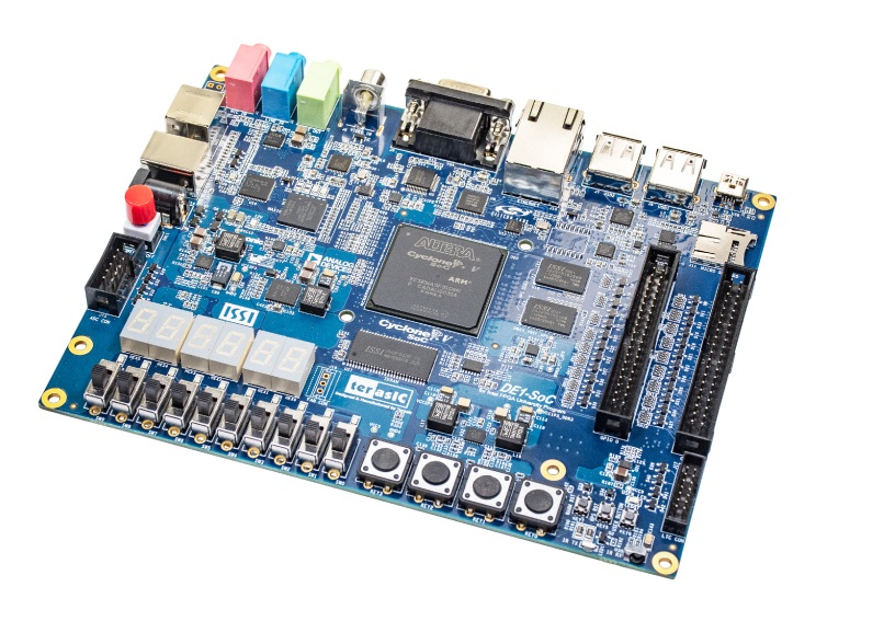
DE1-SoC PLL Example:
// Instantiate PLL IP core
pll my_pll (
    .refclk(CLOCK_50),    // 50MHz input
    .rst(reset),
    .outclk_0(slow_clk)   // Configure for desired frequency
);
Pros: Most accurate, low jitter
Cons: Limited by PLL specifications (minimum frequency typically ~1-5MHz)
5. Combined Approach (PLL + Counter)
Best for: Very low frequencies with good accuracy
-
Use PLL to generate intermediate frequency (e.g., 1MHz)
-
Use counter to further divide down to target frequency
Important Considerations:
-
Clock Domain Crossing: When using generated clocks, properly synchronize signals between domains
-
Glitch Prevention: Generated clocks may have glitches - use clock enables instead where possible
-
Timing Constraints: Always properly constrain generated clocks in your SDC file
DE1-SoC Specific Advice:
-
The board has several PLLs available - check the Cyclone V handbook for specifications
-
For very low frequencies (<1Hz), the counter-based approach is most practical
-
For timing-critical applications, prefer clock enables over generated clocks
Related Articles
- ·Is FPGA chip suitable for algorithm development?
- ·The best MCUs/MPUs for industrial humanoid robots
- ·What are the differences between FPGA and DSP processors for signal processing?
- ·How to become an FPGA engineer? Which FPGA board and program are suitable for beginners?
- ·How to Use DDR Memory with FPGA for DSP Application?
- ·Application of Embedded Systems in Aerospace and Defense Fields
- ·Comparison of FPGA, ARM, STM32, and DSP Platforms
- ·Comparison of FPGA, CPLD, PLC, Microprocessor, Microcontroller & DSP
- ·What is the difference between SoC, FPGA, and ASIC?