


A detailed introduction to VHDL programming language
July 24 2023 
Inquiry
Global electronic component supplier AMPHEO PTY LTD: Rich inventory for one-stop shopping. Inquire easily, and receive fast, customized solutions and quotes.
QUICK RFQ
ADD TO RFQ LIST
This article is going to make detailed introduction about VHDL including basic elements of VHDL, VHDL code simulation, and so on.
What is VHDL?
VHDL is a language used at various levels of abstraction to describe digital electrical circuits. VHSIC (Very High-Speed Integrated Circuits) Hardware Description Language is the name of the acronym VHDL. This means that the design process can be sped up using VHDL. VHDL is NOT a programming language, and this cannot be stressed enough. Therefore, being able to construct digital circuits using its syntax does not necessarily follow from knowing its syntax. Asynchronous and synchronous circuits can be described using the HDL (Hardware Description Language) called VHDL. In particular, VHDL enables the specification of a circuit's functionality via directives, much like most common programming languages do. This permits not just describing a circuit's structure (from simpler subcircuits). Utilizing simulation tools that accurately mimic the operation of the circuit in question, digital circuits that are specified in VHDL can be emulated. Developers employ a set of IEEE-standard rules for this purpose, which describes the syntax of the language and how to simulate it. Additionally, there are numerous programs that convert VHDL code into a file that can be downloaded and used to program a reconfigurable device. Synthesis is the term for this process. A particular tool performs the synthesis process in a precise manner that is significantly different from what other synthesis tools accomplish.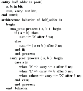
Video related to VHDL programming
Basic elements of VHDL
- Entity of circuit
- VHDL Architecture
- VHDL objects
- Predefined VHDL types
Entity of circuit
A set of generic values that are used to declare the attributes and constants of the circuits, regardless of the architecture, may also be included in the interface that an entity describes. Generics can serve a variety of purposes: They can be used to specify signal and clock cycle delays, on the one hand. (these definitions will not be taken into account at the synthesis level, as explained later throughout this manual). Generics, on the other hand, can also be utilized as constants inside the architecture. These constants contribute to the code's improved readability, portability, and maintainability. For instance, a generic parameter can be used to determine the length of a register (measured in bits). This means that another VHDL code can instantiate this register several times, even if this code instantiates registers with a different number of bits. Generic parameters are not necessary. Hence, a circuit that does not need them simply does not instantiate any generic statement in the entity declaration. The entity of a circuit is described in the example below. This circuit comprises a single output and two N-bit inputs (A and B). (Y). In this instance, the generic statement defining a parameter named N with a value of 8 is included in the entity description. Additionally, the declaration of the circuit inputs uses this parameter.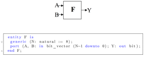
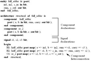
VHDL Architecture
The most basic VHDL building block is the entity/architecture combination. A piece of functionality is defined by the combination of entities and architectures. Each file should have a single entity and architecture. Large FPGA designs are frequently divided into several entity/architect combinations. The port map is contained in the entity. The port map is used to specify each entity's input and output signals. There are three different forms of signals: in, out. The terms "In" and "Out" are self-explanatory; an "In" signal is an input, and an "Out" signal is an output. In general, since inputs are more complex, you shouldn't utilize them until you are comfortable with your FPGA designs.VHDL objects
Constant
Objects that are given an initial value prior to the simulation. Neither during circuit synthesis nor operation is this value allowed to change. They can be stated before the start of a process or before the start of an architecture. The declaration of a constant MUST include a value.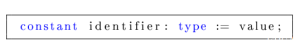
Variable
Objects with a single value that can vary by an assignment statement during simulation or execution. In loops, variables are frequently used as indices or to hold values that can be used to model other components. Neither physical connections nor memory components are represented by variables. They can be stated before the start of a process or before the start of an architecture. A variable declaration COULD or COULD NOT be given a value.![]()
Signal
Objects that represent links between subcircuits or memory components. Signals can be created, in contrast to variables and constants. In other words, the final circuit can physically translate a signal from a VHDL source code into a memory element (flip-flop, register, etc.). Prior to the start of the architecture, they must be declared. Since they represent actual circuit connections, an entity's ports are automatically declared as signals when it is created.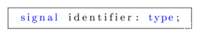
Predefined VHDL types
| std_logic | The IEEE 1164 standard contains a type definition. A multivalued logic with nine different possible values is represented by this type. The most popular ones include, among others, "0," "1," "Z" (for high impedance), "X," "U," and "U" (for undefined). |
| std_logic_vector (range) | It represents a vector of objects with std_logic type members. The rules for assignment and definition are identical to those of std_logic. |
| bit | It accepts only the numbers 0 and 1. The value must be enclosed in single quotes (either "0" or "1") in order to be assigned to the object. |
| bit_vector (range) | The bit_vector, which is an array of 0s and 1s, has a fixed number of bits, which is indicated by the range, which is always written within brackets. An n-bit bit_vector must specify its range using the notation N-1 down to 0. The most significant bit (also known as the MSB) is found on the far left, and the least significant bit is found on the far right. (Least Significant Bit or LSB). The value must be written in between quotation marks in order to make an assignment between the item and it. (i.e., "0011"). |
| real range | Any genuine number is falling inside the range. The range is not required. |
| positive range | Anything within the range that is positive. The range is not required. |
| natural range | Any natural number within the range. The range is optional. |
| integer range | Any integer number that falls within the range and is not in this case enclosed in brackets. Consider the range 0 to MAX. The range is not required. |
| string | Any string made entirely of ASCII characters. |
| character | It can take any ASCII value. |
| boolean | It only can take the values true or false. |
VHDL code simulation
Steps of simulation
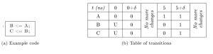
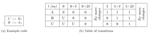
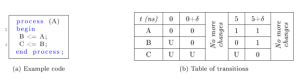
- Step 0: The time count is set to 0 and all signals are initialized.
- Step 1: All scheduled transitions are completed at that time.
- Step 2: In the list of events, all the signals that are changed as a result of transitions that happen at instant = t are noted and scheduled for instant = t +, where is an infinitesimal.
Simulation statements
The wait statement, which is available in VHDL, halts the simulation of the code until a condition is satisfied. If a process lacks a sensitivity list, it must include a wait statement. Additionally, wait statements can be used to build sequential hardware. Three different wait statements exist:- wait on list_of_signals; if any signal in the list_of_signals is updated, the simulation resumes.
- wait for time; the simulation pauses for the amount of time indicated by the time variable.
- wait until the condition is met; until the condition is satisfied, the simulation runs.
Simulation templates in VHDL
A graphical user interface (GUI) is often included in simulation and synthesis programs to make it easier to assign the stimulus to the circuit inputs and test the design's functionality. However, building a test bench directly using VHDL for complex circuits and huge test benches is much more practical. The testbench will ultimately be a VHDL file that has an entity without any inputs or outputs that instantiates two processes and a component, as shown in Figure 11, whether the testbench was generated using the GUI or by typing it directly. The latter really creates the test circuit.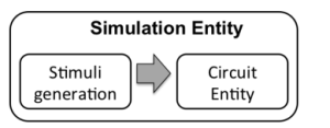
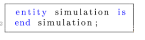
An entity without any inputs or outputs must be created
Template for VHDL Architecture
The methods and components of the circuit being tested (if any), as well as the architecture, are discussed. The following is a potential template for the method of setting stimuli to the input signals of the circuit being tested: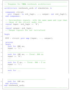
Signal simulation
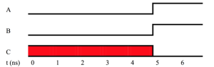
The input signal is kept at its starting value ('0') for the first 200 ns thanks to the first wait in the code (wait for 200 ns;). The subsequent statements, including the assignment input = "1," are then carried out. This updated value is retained for a further 100 ns by the second wait (wait for 100 ns). Another illustration is the code below: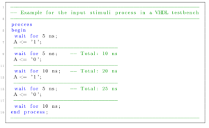
Template for the process that defines the clock
This method generates a signal (clk), whose value is set alternately to "0" and "1," depending on the times provided in the time_low and time_high constants, through the use of the loop statement. For the first 10 ns, the first wait statement maintains the initial value of CLK. The second delay shows when clk is set to its low value ('0'), after that. The last wait shows when clk was last set to its high value ('1'). This pattern keeps happening forever. Note that the loop statement makes this possible. Actually, there is a small difference between this and the statements in the for-loop and while-loop.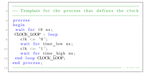
Populer Posts
LFXP2-30E-5FN484I
Lattice Semiconductor
XC17V01SO20I
AMD
M2GL060TS-FCS325
Microsemi
XC18V01-10VQ44C
AMD
M2S025T-1VFG256I
Microsemi
XC2S50-7PQ208C
AMD
M5-192/68-15VC-20VI/1
Lattice Semiconductor
XC2VP70-FFG1517C
AMD
M5-512/256-7AC-10AC
Lattice Semiconductor
XC1765DDD8M
AMD
PALCE16V8H-25/PC
Lattice Semiconductor
XC2VP7-6FFG456I
AMD