


How to Test A Relay?
September 12 2023 
Inquiry
Global electronic component supplier AMPHEO PTY LTD: Rich inventory for one-stop shopping. Inquire easily, and receive fast, customized solutions and quotes.
QUICK RFQ
ADD TO RFQ LIST
By understanding how relay works and how to test it, you can ensure that your electrical circuits are functioning properly and avoid any potential problems that may arise due to faulty relays.
What is A Relay?
A relay is an electrical switch that uses an electromagnet to control the opening and closing of its contacts. When a current passes through the coil of the electromagnet, it generates a magnetic field that attracts the armature, causing it to move and close or open the contacts. It is commonly used to control high-power circuits with low-power signals, allowing for the isolation and protection of sensitive components. Relays find widespread use in different applications for the purpose of managing high-power circuits or isolating low-power circuits from high-power circuits. They offer a means to regulate electrical loads by utilizing a control signal of lower power, for instance, a digital signal or a switch. Relays are commonly used in various applications to control high-power circuits or to isolate low-power circuits from high-power circuits. They provide a way to control electrical loads using a lower-power control signal, such as a switch or a digital signal. There are different types of relays available, including electromagnetic relays, solid-state relays, reed relays, thermal relays, and more. Each type has its own characteristics and is suitable for specific applications based on factors such as switching speed, current rating, voltage rating, contact materials, and environmental conditions.How Does A Relay Work?
A relay works by using an electromagnet to control the position of its contacts. When a current flows through the coil of the relay, it creates a magnetic field that attracts the armature, which in turn moves the contacts from their normally open (NO) to their normally closed (NC) position, or vice versa. This allows the relay to switch between two different circuits, one with the contacts closed and one with the contacts open, depending on the state of the coil. Relays can be designed to operate on AC or DC voltage and can be configured to switch a wide range of loads, including motors, lights, and other electrical devices. By controlling the current through the coil, the relay can effectively switch high-power circuits or isolate low-power circuits. This allows relays to be used in various applications where electrical isolation, high-power switching, or control over multiple circuits is required.How to Wire A Relay?
Wiring a relay involves connecting the relay to a power source, the load (device or circuit you want to control), and a control signal source. Here's a general guide on how to wire a relay: Understand the Relay Pins: Relays typically have multiple pins or terminals. The most common types of relay pins are:- Coil Pins: These are the pins connected to the coil of the relay, usually labeled as "Coil" or "C" with a positive (+) and negative (-) designation. The coil pins are used to apply the control signal to activate the relay.
- Normally Open (NO) and Normally Closed (NC) Contacts: These are the pins associated with the relay's contacts. The NO pin is labeled as "NO," while the NC pin is labeled as "NC."
- Normally Open (NO) Connection: Connect one side of the load to the common (COM) pin of the relay and the other side to the normally open (NO) pin of the relay.
- Normally Closed (NC) Connection: Connect one side of the load to the common (COM) pin of the relay and the other side to the normally closed (NC) pin of the relay.
How to Test A Relay?
Relays are important electrical components that are used to control high-power circuits with low-power signals. They work by using an electromagnet to switch the position of their contacts, allowing them to switch between two different circuits. However, like any other electrical component, relays can become faulty over time due to a variety of factors such as overheating, damage to the contacts, or a malfunctioning coil. To determine if a relay is bad, there are a few common signs to look out for. These include failure to operate, overheating, abnormal clicking sounds, burnt or damaged contacts, and inconsistent performance. To test a relay, it is important to first disconnect it from the circuit to avoid interference from other components. Then, you can use a multimeter to check the resistance of the coil and the continuity of the contacts. By applying power to the coil and checking for continuity between the contacts in both positions, you can determine if the relay is functioning properly or not. It is important to also inspect the relay for any physical damage, such as burnt or damaged contacts, cracked housing, or other signs of wear and tear. In the next part, I will further explore how to test a relay with a multimeter.How to Test A Relay with A Multimeter?
Testing a relay using a multimeter is a straightforward process that involves examining the continuity or resistance of the relay's coil and contacts. Here is a step-by-step guide on how to test a relay using a multimeter: First and foremost, it is crucial to prioritize safety by ensuring that the relay is disconnected from any power source or circuit before initiating any testing. This precautionary measure helps avoid potential electrical hazards during the testing process. Next, set your multimeter to the appropriate mode, either continuity or resistance. If you have a digital multimeter, select the corresponding mode and range suitable for the test. Identify the various pins of the relay. Typically, relays consist of coil pins, often labeled as "+" and "-," and contact pins, including COM, NO, and NC. To test the relay's coil, place the multimeter probes on the coil pins. The positive probe should be connected to the positive coil pin, while the negative probe should be connected to the negative coil pin. In the continuity mode, a beep or continuity indicator should be observed if the coil is intact. In the resistance mode, a low resistance reading, close to the manufacturer's specified coil resistance, indicates a functioning coil. Conversely, the absence of continuity or a high resistance reading suggests a faulty coil. Moving on to testing the contacts, connect the multimeter probes to the common (COM) and normally open (NO) pins of the relay. In its resting state (not energized), there should be no continuity or a high resistance reading between the COM and NO pins, indicating that the contacts are normally open. To evaluate the contacts' behavior when the coil is energized, apply power to the relay's coil by connecting it to a power source or supplying the appropriate control signal. Once the coil is energized, recheck the continuity or resistance between the COM and NO pins. At this point, continuity or a low resistance value should be observed, signifying that the contacts have properly closed. Additionally, you can repeat the process by connecting the multimeter probes to the common (COM) and normally closed (NC) pins. In the resting state, continuity or a low resistance reading should be present. However, when the coil is energized, there should be no continuity or a high resistance reading between COM and NC, indicating that the contacts have opened correctly. If desired, you can verify the relay's switching operation by connecting it to a test circuit or load, such as a light bulb. Ensure that the load is properly connected according to the relay's specifications. This step allows you to observe the relay's ability to switch the load on and off effectively while simultaneously testing the coil and contacts. By following these step-by-step instructions and correctly interpreting the multimeter measurements, you can confidently test a relay using a multimeter. It is always advisable to consult the relay's datasheet or specifications for any specific instructions or parameters, as different relay models may possess unique characteristics and testing requirements.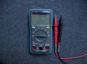
How to Tell A Relay is Bad?
Numerous indications can suggest a defective or inadequate relay. The following are some typical cues to be mindful of:
4 Pin Relay Wiring Diagram
A 4-pin relay is a commonly used type of relay that provides a simple and effective way to control electrical circuits. Here is a basic wiring diagram for a 4-pin relay: Pin 85: Connect to the ground or negative side of the power source. Pin 86: Connect to the positive side of the power source. Pin 87: Connect to the device or circuit that you want to control. Pin 30: Connect to the positive side of the power source.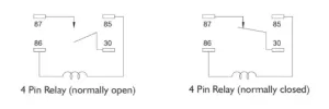
5 Pin Relay Wiring Diagram
The pin relay is a type of relay that has single pole double throw contacts, also known as SPDT contacts. A 5-pin relay is another commonly used type of relay that provides additional functionality compared to a 4-pin relay. Here is a basic wiring diagram for a 5-pin relay: Pin 85: Connect to the ground or negative side of the power source. Pin 86: Connect to the positive side of the power source. Pin 87: Connect to the device or circuit that you want to control when the relay is energized. Pin 87a: This pin is not used in a standard 5-pin relay and is usually left unconnected or unused. Pin 30: Connect to the positive side of the power source.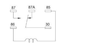
Conclusion
In conclusion, testing a relay is a crucial step in ensuring its proper functionality and reliability. By using a multimeter, we can perform a comprehensive evaluation of the relay's coil and contacts. Testing the coil involves checking for continuity or resistance, and ensuring its integrity. Examining the contacts involves verifying their normal open (NO) and normally closed (NC) states, as well as their switching operation when the coil is energized. Following the appropriate steps and interpreting the multimeter readings accurately allows us to identify any potential faults or malfunctions in the relay. Ultimately, conducting thorough relay testing promotes electrical safety and enables us to maintain efficient control over electrical circuits and devices.Related Articles
- ·How does JTAG work for FPGAs?
- ·What are the differences between popular MCU families (e.g., ARM Cortex-M, AVR, PIC, ESP32)?
- ·Altera vs Xilinx vs Lattice, Cost effectiveness comparison
- ·How do you choose the right sensor for a project?
- ·What are some common Arduino projects for beginners?
- ·How do you set up a Raspberry Pi as a VPN server?
- ·How are FPGAs used in AI/ML applications?
- ·STM32 four precision control methods for stepper motors
- ·What is the lowest power STM32 MCU? how to choose?
- ·How to boot Linux on a Xilinx FPGA?
Populer Posts
ADSP-2187NKST-320
Analog Devices Inc.
AD21478WYSWZ2B02
Analog Devices Inc.
ADSP-21478BSWZ-2A
Analog Devices Inc.
RZTHC6748
Texas Instruments
TMS320C15NL
Texas Instruments
TNETV2685VIDZUTA9
Texas Instruments
ADSP-BF518BBCZ-4
Analog Devices Inc.
ADSP2115KP-80
Analog Devices Inc.
ADSP-2101BP-40
Analog Devices Inc.
SAA7706H/N210,518
NXP Semiconductors
ADSP-21573CBCZ-5
Analog Devices Inc.
ADSP-2171BSTZ-133
Analog Devices Inc.